From DD-WRT Wiki
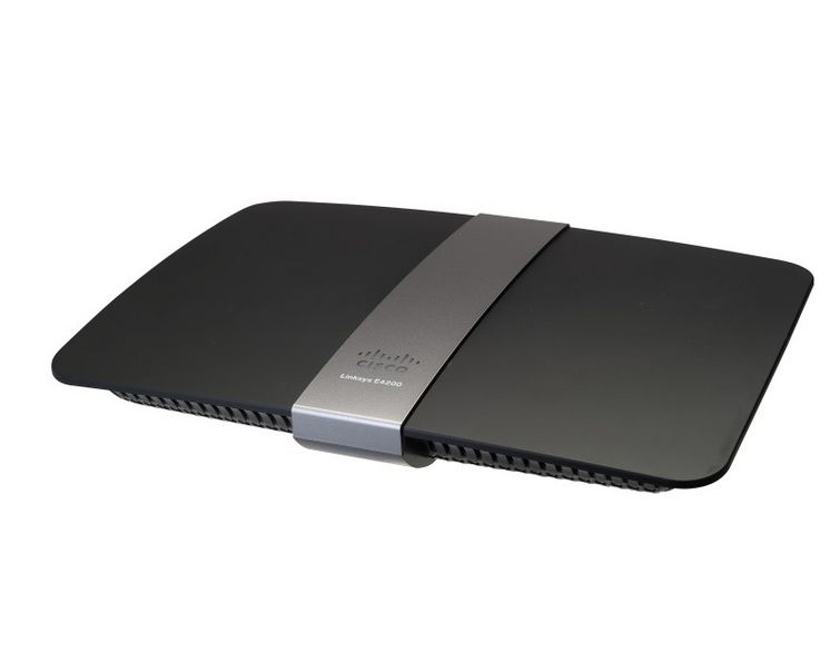
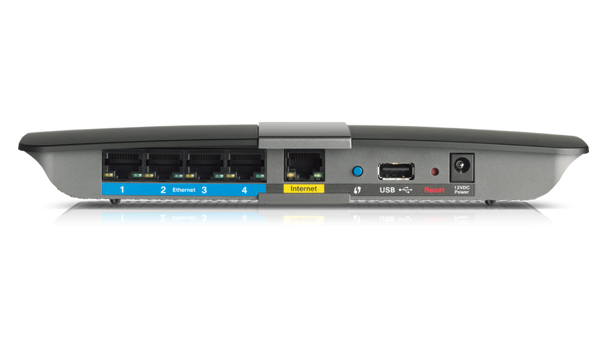
Download the latest E4200 firmware from linksys site. Disconnect all cables and wireless clients. Perform a 30/30/30 reset on the device. Login and select the stock firmware file and flash, make sure to select 'reset to defaults' on the drop down menu when flashing. Wait approximately 5 minutes for the flashing process to complete. The E4200 also marks the first radical change in the design of the Linksys series since Cisco launched the winged 'spaceship' design first seen on the WRT400N. The E4200 features a minimalistic, streamlined design with only a white status LED visible on the top. All traffic activity LEDs and buttons have been relocated to the rear of the device. Linksys WRT AC Series Introduction The Linksys WRT AC series is a set of high performance, multi-core, 802.11ac capable devices, designed to be supported by OpenWrt out of the box, and the OEM firmwares are based off of OpenWrt. All of the devices use the mwlwifi driver, an open source driver with closed source firmware. Note that the development of the mwlwifi driver has been stopped in early.
English • Deutsch • Español • Français • Italiano • 日本語 • Polski • Português • Русский • Svenska • 中文(中国大陆) • 中文(台灣) • |
|
[edit]Introduction
Routers with a serial port AND working CFE (bootloader) can often be recovered with a serial adapter, using CFE low-level commands. Otherwise JTAG is required to debrick, if available, which can also replace a corrupted CFE. The last resort is to desolder the flash chip and use a programmer to flash CFE (if needed) and firmware.
Serial ports are normally four or five pins on the router board. Unless it has an OEM header, you have to either solder the wires to the pads, or remove solder from the holes to install an appropriate header. Some routers have serial ports inside the WAN port, and here is a link to some Serial port pinouts.
[edit]Redhawk0 summary
Serial cable can be either USB or DB9 connection type and be capable of voltage level shift to +3.3V, not +5V. There are three or four connections for serial to function properly: Vcc (+3.3V, but usually not connected), GND, Tx and Rx. Some boards are NOT marked with pin designation, so use a multimeter to determine power and ground to avoid shorting the serial cable TTL chip. Then you can guess at the Rx and Tx lines. Rx and Tx are labeled relative to the cable, so Rx line needs connected to the router's Tx, because the router labels are also relative to it, so Tx and Rx get crossed for proper connection. On routers with two Serial ports (Tx0/Tx1 and Rx0/Rx1), use the '0' ports for your connections (I've not seen a router yet that connects to the '1' side).
[edit]Command Terminals
You connect and talk to the router from a PC using terminal/console programs such as:
- PuTTY (All), HyperTerminal (WinXP and older), minicom (Linux), picocom (Linux), terminalbpp (Win)
Terminal settings:
HyperTerminal in Windows XP: Start Button->All Programs->Accessories->Communication->HyperTerminal
- To save the configuration, click File-->Save As, and select a save location
Putty: check the Device Manager (Win) or `dmesg` output (Linux) for the COM port name
- Select Serial under Connection, use the port used for serial (e.g. COM3 in Windows)
- To save the configuration: Click Session, enter a name for your connection under saved sessions, Save
[edit]Serial Interfaces
You NEED a level shifting 3.3v TTL serial adapter. This is a special serial adapter. YOU CANNOT USE A SERIAL ADAPTER THAT IS NOT LEVEL SHIFTING! The Nokia CA-42 cable is a level shifting serial adapter. Other proper serial adapter are available from ebay and amazon and other online sources. You can get Nokia CA-42 cables online for about 3.00 and cut the phone end off. Then you have to figure out what each wire does. You need only grd, tx and rx connected properly for the serial interface to work. Tx on the adapter goes to rx on the router and rx on the adapter goes to tx on the router.
See this picture: You only need the wires connected to pins 8, 7, and 6.
- If no wire is connected to pin 8, the pin marked pin 2 in this picture should be ground instead.
Here is what redhawk0 did:
- I cut the connector end off and found 3 wires: Blue, Red, and Orange.
- Using an Ohm meter I determined that the Orange wire is Ground.
- Using the 'guess' method, the Blue wire connects to the router Rx and Red connects to router Tx
- The cable was not recognized in XP and no drivers found during the PnP process.
- I downloaded a utility determining the attached hardware UVCViewer
- Then downloaded the Prolific driver
- The updated 1.4.17 driver supposedly provides better support for Vista/Win7.
- Once loaded and connected, my laptop sees the unit attached to COM8 to configure Putty, and all is well.
[LOM] No there is no fixed standard for the colours of the wires and obviously not on the number of wires either. My first CA-42 had 3 wires and the ones I bought later had 5, the picture in my post above is from one of those.You can carefully remove the plastic molding of the phone connector and see where each wire is going and find out which colour the respective signals are on. Nokia phone connector: Schematic
[strfr] The 'level shifting 3.3v TTL adapter' is a must, you can't connect router straight to standard RS232 serial interface. Cheap CA-42 is ok, even the Chinese clone with ARK3116 chip, thus you will not find proper driver for Win7 64bit system. Windows XP mode is the solution in such a case.
[Malachi] I have purchased a few of the Nokia clones that didn't work, for that reason I buy USB to uart adapters like these.
[edit]Break CFE Boot
'There is less than a second at power-up to break CFE and stop the boot, thus allowing keyboard entry in a terminal. Do this by rapidly hitting Cntl-C (tpl for TP-Link routers) JUST as the router is starting up. The time window to do this is less than a second or two. It helps to get someone to help with this process, or have good dexterity.
NOTE: Ensure the Scroll Lock key is off and Flow Control is off or none, or the boot will not stop.
[edit]CFE Commands
To see the built-in CFE default parameters (restored after a `nvram erase` or reset):
`devinfo set {parameter}='{value}' can be used to change values.
To list the devices and descriptions:
[edit]Nvram Parameters
These can be checked with `nvram show`. Also see Hardware#NVRAM
`nvram set {parameter}='{value}' can be used to change values.
[edit]Erase Nvram
The most common CFE command is 'nvram erase'. Bad nvram values are often the cause of bricked routers.
NOTE: the OS (Linux->DD-WRT) reset command Hard_reset_or_30/30/30#Erasing_NVRAM depends on the build/date.
At the cfe prompt:
In some cases more specific commands may be required for recovery. Do a `show devices` first. E.g.:
[edit]To flash the firmware

This assumes a ttl adapter is connected and ready. There is reference to stock firmware. This does not apply to routers that ran VxWorks on OEM firmware, as they should have jtag.
Connect the router to your serial adapter with com parameters: 115200, 8, 1, n, no flow control
Watching the terminal window, boot the router and immediately start hitting ctrl-c to get the cfe prompt:
Execute the nvram erase command at the CFE prompt. It may also help to erase linux to debrick.
Prepare the tftp utility to flash the STOCK firmware for your router so all you need to do is hit enter to launch.
Now to get the router to accept a tftp flash for the firmware. It times out quickly so get the utility ready to launch!
Static IP: 192.168.1.10, mask 255.255.255.0, not necessary but gateway 192.168.1.1
If you have a Linksys router, at the cfe prompt:

For other routers try:
Another option to try is to manually force the TFTP daemon:
Hit enter and the router will wait for firmware upload. It will time out after three tries, so now launch the tftp utility to upload, program, then return to the cfe prompt. This will take some time, and the console can be monitored for the status.
You will be back at the cfe prompt when it is done:
Linksys E4200 Manual
Issue a 'go' command:
The router will launch its new firmware. Let it boot: 2 ~ 3 times. Now reinstall DD-WRT.
[edit]Barryware Instructions for Linksys
Start banging ctrl-c at the same time you power up the router. If successful, you will be at the cfe prompt:cfe>have your tftp utility all que'd up to flash the STOCK LINKSYS firmware for your router. Make sure you have a static ip on your rig.. The router will not have the dhcp server running.At the cfe prompt type:
a couple of seconds later, you will get a command status = 0.. that is good. You will be back at the cfe prompt.Now type:
(note the space before & after the colon)Now immediately launch the tftp utility on your computer. The router will listen 3 times, after that it will time out so you gotta be fast.You will see that it is programming.. this will take a bit of time. When it is done, you will again be back at the cfe prompt.After the flash chip is programmed and you are back at the cfe prompt, either power cycle the router (I prefer) or type:
the router will boot three times. then you are good to go with stock firmware. From there, install dd-wrt again following the normal procedures.Have fun.. Good luck

One more time, for those who need repetitive instructions:
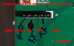
Linksys E4200 Serial Pinout Location
- Serial is to communicate with the router and issue the commands.
- All data to flash goes through the lan ports.
- Stop the boot via ctrl-c (You have to be faster than humanly possible to hit ctrl-c fast enough!)
- Tell it to accept a tftp upload of the firmware (through the lan port(s) (eth0)) by issuing the command:
flash -ctheader : flash1.trx [then press enter key] - Immediately launch the tftp utility on your computer and send the proper firmware to the router.
- It times out very fast so issue the command and immediately launch the utility.
- Flash stock linksys firmware when debricking a router. (You can flash dd-wrt again, following the wiki instructions for your model of router.
When back at the cfe prompt:
The router will boot 3 times. Don't be scared.
[edit]LOM on the E3000
The easiest way of flashing an E3000 when you have serial terminal attached is:
Then open 192.168.1.1 to the CFE recovery GUI page where you can upload the firmware.
[edit]Troubleshooting
Some USB ttl converters also need Vcc connected, but most only need Tx, Rx, and ground.
If you are unable to write data to the flash chip due to a bad boot block, try writing to another location. This should be done with caution as a last resort.
Find the 'Boot partition size =' at the cfe boot (just under Initializing Devices in my case), to get the flash command address location offset: Boot partition size = 262144(0x40000)
So for my Windows PC at 192.168.2.10, hosting the firmware via a tftp server:
The command above tells the cfe to flash the firmware at a particular address location on the flash chip, instead of the location that the cfe thinks is the correct one, which obviously is not if it reports a bad boot block.
If you receive no output, remove the Tx & Rx wires from the router and twist them together. Open a terminal session and type something to see if the characters are echo'd correctly in the terminal. If you see what you typed, the COMPUTER is set up properly, so check the router connection next. If still is no output, the problem is with the computer setup. Check your com parameters. Depending on the hardware & driver, you may have to set Device Manager parameters, as well as your terminal software.
Cisco Linksys E4200
Garbage characters on the screen usually is a bad connection, especially a bad ground. Also try swapping the Tx and Rx. Recheck your connections with a multimeter.
If you cannot get a cfe prompt it is usually due to not being fast enough. Get someone to assist in turning on the router while you hit control c over and over again as fast as superman or Barryware. If that doesn't work try reversing the tx and rx to make sure that you are actually transmitting the command.
[edit]Links
Serial Thread from the Broadcom forum.